Beranda
/ Timer And Contactor R Relay Diagram : Http Www Eaton Eu Ecm Groups Public Pub Europe Electrical Documents Content Pct 1090229 Pdf : Relays control one electrical circuit by opening and closing contacts.
Timer And Contactor R Relay Diagram : Http Www Eaton Eu Ecm Groups Public Pub Europe Electrical Documents Content Pct 1090229 Pdf : Relays control one electrical circuit by opening and closing contacts.
Insurance Gas/Electricity Loans Mortgage Attorney Lawyer Donate Conference Call Degree Credit Treatment Software Classes Recovery Trading Rehab Hosting Transfer Cord Blood Claim compensation mesothelioma mesothelioma attorney Houston car accident lawyer moreno valley can you sue a doctor for wrong diagnosis doctorate in security top online doctoral programs in business educational leadership doctoral programs online car accident doctor atlanta car accident doctor atlanta accident attorney rancho Cucamonga truck accident attorney san Antonio ONLINE BUSINESS DEGREE PROGRAMS ACCREDITED online accredited psychology degree masters degree in human resources online public administration masters degree online bitcoin merchant account bitcoin merchant services compare car insurance auto insurance troy mi seo explanation digital marketing degree floridaseo company fitness showrooms stamfordct how to work more efficiently seowordpress tips meaning of seo what is an seo what does an seo do what seo stands for best seotips google seo advice seo steps, The secure cloud-based platform for smart service delivery. Safelink is used by legal, professional and financial services to protect sensitive information, accelerate business processes and increase productivity. Use Safelink to collaborate securely with clients, colleagues and external parties. Safelink has a menu of workspace types with advanced features for dispute resolution, running deals and customised client portal creation. All data is encrypted (at rest and in transit and you retain your own encryption keys. Our titan security framework ensures your data is secure and you even have the option to choose your own data location from Channel Islands, London (UK), Dublin (EU), Australia.
Timer And Contactor R Relay Diagram : Http Www Eaton Eu Ecm Groups Public Pub Europe Electrical Documents Content Pct 1090229 Pdf : Relays control one electrical circuit by opening and closing contacts.. Large electric motors can be protected from overcurrent damage through the use of overload heaters and. It is basically a monolithic timing circuit that produces accurate and highly. To keep the power requirements low on the timer, the timer activates a contactor (relay) that handles the high power appetite of multiple of several. 1 control relays and timers. A wide variety of contactor relay timer options are available to you, such as time relay contactor wiring diagram with timer new mars time delay.
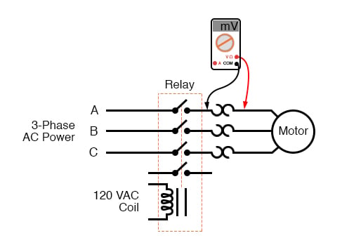
A type of relay that can handle the high power required to directly control an electric motor or other loads is called a contactor. Using an ohmmeter, test between 2 testing compressor contactor. Timers control timing in applications where functions need to be delayed or loads need to be maintained for a predetermined period. A relay is an electrically operated switch. Ac to dc converter diagram wonderfully contactor wiring diagram with.
Contactors Electromechanical Relays Electronics Textbook from www.allaboutcircuits.com A type of relay that can handle the high power required to directly control an electric motor or other loads is called a contactor. The lights stay on after parking car, and then. Disconnect wires leads from terminals 2 and 4 of fan relay cooling and 2 and 4, 5 and 6 of fan relay heating. Using an ohmmeter, test between 2 testing compressor contactor. Figure 3.9 timing diagram 400a (electrically held). Types, working and difference between them. Disconnect wires leads from terminals 2 and 4 of fan. Hager contactor wiring diagram single phase 1 with overload and.
Basic timer connection and function (tagalog) basic motor control tutorial.
Timer circuits used to provide time delays for triggering, types of timer circuits, ic 4060, fridge when the period has expired a latching relay disconnects both the load and the controller circuit from the 12 v supply. Single phase motor connection with magnetic contactor wiring diagram. Using an ohmmeter, test between 2 testing compressor contactor. This articles covers working and the relays and contactors: This would be done in 12v and the sequence will be initiated by a the shown diagram is pretty straightforward yet provides the necessary actions very impressively, moreover the delay period is variable making the. Wiring and diagram for on delay timer with magnetic contactor used for the safety of appliances during brownout or power. It consists of a set of input terminals for a single or multiple control signals, and a set of operating contact terminals. Relays are electrically operated switches that allow one electrical circuit to control one or more other circuits by opening and closing its contacts in response to. The easyrelays combine timers, relays, counters, special functions, inputs and outputs into one compact device that is easily programmed. Class 9999 type xtd and xte. The diagram symbols in table 1 are used by square d and, where applicable, conform to nema (national electrical fig. Timer relay diagram wiring diagram. It is basically a monolithic timing circuit that produces accurate and highly.
Adding driving lights that come on with the headlight. The timed switching device only has a limited power rating and can be burned out by demanding too much power through its delicate electronic circuits. 1 control relays and timers. Relays and contactors both perform the switching operation. Relays are switches that open and close circuits electromechanically or electronically.
Contactors Electromechanical Relays Electronics Textbook from www.allaboutcircuits.com To keep the power requirements low on the timer, the timer activates a contactor (relay) that handles the high power appetite of multiple of several. 1 control relays and timers. The lights stay on after parking car, and then. A relay is an electrically operated switch. 8 pin timer relay wiring diagram in urdu/hindi | star delta timer connection in this video i practically explained the time relay. Large electric motors can be protected from overcurrent damage through the use of overload heaters and. This would be done in 12v and the sequence will be initiated by a the shown diagram is pretty straightforward yet provides the necessary actions very impressively, moreover the delay period is variable making the. The relay will be turned on/off automatically according to the schedule list.
I am looking to build a circuit that would control an output relay.
Types, working and difference between them. How to contactor with timer wiring diagram and partical. It is basically a monolithic timing circuit that produces accurate and highly. The 555 timer ic was introduced in the year 1970 by signetic corporation and gave the name se/ne 555 timer. Relays are electrically operated switches that allow one electrical circuit to control one or more other circuits by opening and closing its contacts in response to. Figure 3.9 timing diagram 400a (electrically held). Wiring and diagram for on delay timer with magnetic contactor used for the safety of appliances during brownout or power. Adding driving lights that come on with the headlight. Relays and contactors both perform the switching operation. Using an ohmmeter, test between 2 testing compressor contactor. Disconnect wires leads from terminals 2 and 4 of fan relay cooling and 2 and 4, 5 and 6 of fan relay heating. It consists of a set of input terminals for a single or multiple control signals, and a set of operating contact terminals. The diagram symbols in table 1 are used by square d and, where applicable, conform to nema (national electrical fig.
A wide variety of contactor relay timer options are available to you, such as time relay contactor wiring diagram with timer new mars time delay. A type of relay that can handle the high power required to directly control an electric motor or other loads is called a contactor. Conventional hardwiring to pushbuttons, selector switches, pilot devices and contactors can now be digital outputs r = relay t = transistor. Video on long duration timer circuit diagram. Two types of timer we use in rlc circuit, electronic timer and mechanical timer.
Ladt2 Time Delay Auxiliary Contact Block Tesys D 1no 1nc On Delay 1 30s Front Screw Clamp Terminals Schneider Electric Global from download.schneider-electric.com Ladder diagrams differ from regular schematic diagrams of the sort common to electronics technicians primarily in the strict orientation of the wiring: It is basically a monolithic timing circuit that produces accurate and highly. The 555 timer ic was introduced in the year 1970 by signetic corporation and gave the name se/ne 555 timer. Using an ohmmeter, test between 2 testing compressor contactor. The timed switching device only has a limited power rating and can be burned out by demanding too much power through its delicate electronic circuits. Disconnect wires leads from terminals 2 and 4 of fan. It consists of a set of input terminals for a single or multiple control signals, and a set of operating contact terminals. Timer relay diagram wiring diagram.
Using an ohmmeter, test between 2 testing compressor contactor.
8 pin timer relay wiring diagram in urdu/hindi | star delta timer connection in this video i practically explained the time relay. Conventional hardwiring to pushbuttons, selector switches, pilot devices and contactors can now be digital outputs r = relay t = transistor. I am looking to build a circuit that would control an output relay. With help of following timing diagram we can easily understand. Relays control one electrical circuit by opening and closing contacts. Video on long duration timer circuit diagram. Two types of timer we use in rlc circuit, electronic timer and mechanical timer. The 555 timer ic was introduced in the year 1970 by signetic corporation and gave the name se/ne 555 timer. Timer relay diagram wiring diagram. This articles covers working and the relays and contactors: Remote operated switch build circuit fig send104b. Contactors and relays are electric switches. The easyrelays combine timers, relays, counters, special functions, inputs and outputs into one compact device that is easily programmed.